
- OBJECTIVE:
To lay down a procedure for to perform periodic Revalidation of Air Handling Unit in Fluid Bed Processor /Drier / Equipment and Automatic Coating Equipment.
- SCOPE:
This SOP is applicable for to perform periodic Revalidation of Air Handling Unit in Fluid Bed Processor /Drier / Equipment and Automatic Coating Equipment {Company Name} {Company Location}.
- RESPONSIBILITY:
- Technical Assistant – Engineering to perform periodic Re-validation activities.
- Executive – Engineering to monitor the periodic Re-validation activities for compliance of SOP.
- Executive – Validation – Quality Assurance to monitor and review the periodic Re-validation activities.
- Head Engineering/Designee – To review the periodic Re-validation activities.
- Head Production/Designee – To review the periodic Re-validation activities.
- Head Quality Assurance/Designee – To review and approve the periodic Re-validation activities.
- ACCOUNTABILITY:
Engineering Head
Head Quality Assurance
- PROCEDURE:
- Revalidation of Air Handling Unit in Fluid Bed Processor/Drier/ Equipment and Automatic Coating Equipment
- This SOP covers Periodic Revalidation activities for Air Handling Unit in Fluid Bed Processor / Drier/Equipment and Automatic Coating Equipment.
- In case of any Modification in the Air handling unit for Fluid Bed Processor / Drier/Equipment and Automatic Coating Equipment which have an impact on validated system, a new protocol shall be prepared and executed.
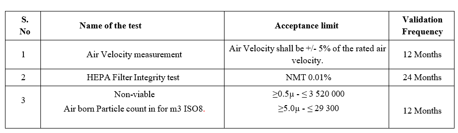
- The following test parameters shall be performed during periodic revalidation as per the defined frequencies.
- HEPA Filter Integrity test.
- Air Velocity Measurement
- Non-viable Particle Count test
- The test parameters along with acceptance criteria and frequencies is mentioned below.
- Grace period for frequencies of Revalidation tests.
The Revalidation tests shall be performed as per the below frequencies and grace period.
| S. No | Validation Frequency | Grace Period |
| 1. | 12 Months | ± 15 days |
| 2 | 24 Months | ±30 days |
- However, in case of in case of any Modification in the Air handling unit for Fluid Bed Processor / Drier/Equipment and Automatic Coating Equipment which have an impact on validated system, a new protocol shall be prepared and executed immediately ,ones after modification activity is completed.
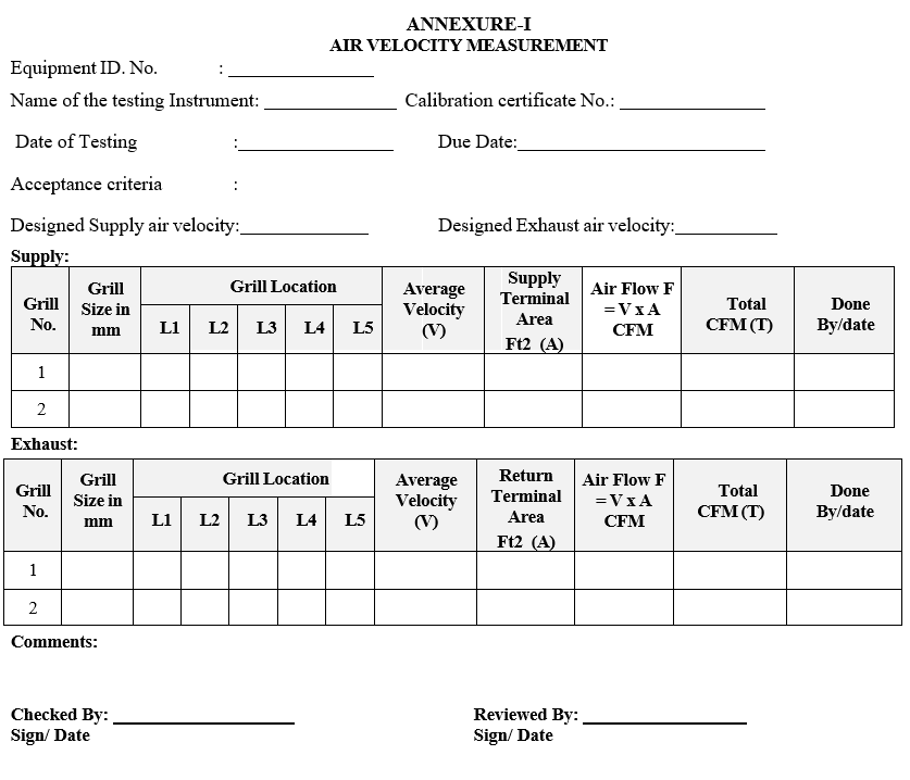
- AIR VELOCITY MEASUREMENT
- Ensure that the blowers of the respective equipment are switched “ON” prior to the start of the air velocity test.Measure the air velocity at 5 locations of the supply air filter/ Grill (Four Corners and centre) with the Anemometer and record.Calculate the average velocity of the air coming from Supply Grill.
- Calculate the airflow by multiplying the average velocity with the effective filter area.
- AIR VELOCITY MEASUREMENT
- Air flow (F) = Average Velocity x Face Area of the Air supply Grill / Filter
= Ft / Min. X Ft 2
= Ft 3 / Min. or CFM
- Calculate the airflow for all the Supply Grill and record the results in Annexure-I.
- Repeat the above procedure for Return air grill wherever applicable and record the observation in Annexure-I.
Click the link to download word file copy of this document:
https://pharmaguidehub.com/product/revalidation-of-air-handling-unit-in-fluid-bed-processor-drier-equipment-and-automatic-coating-equipment/
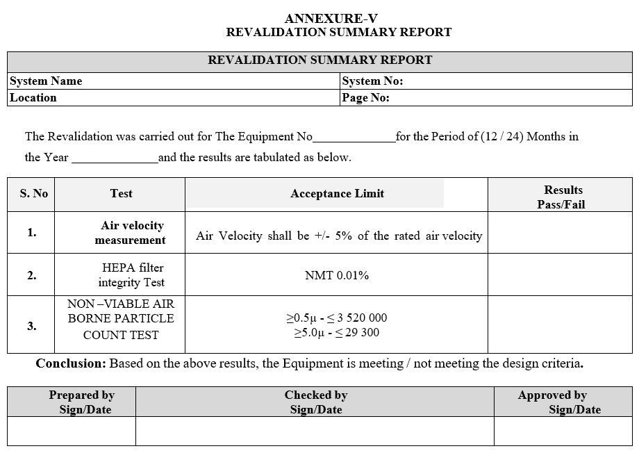
Acceptance criteria: Air Velocity shall be +/- 5% of the rated air velocity.
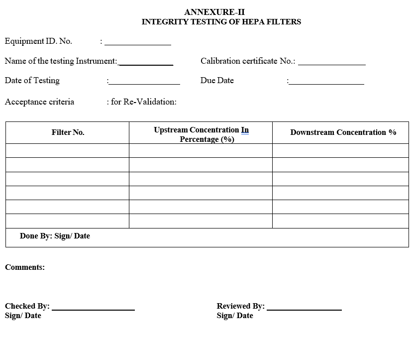
- HEPA Filter integrity test:
- Duly calibrated Aerosol photometer shall be used for filter integrity test and Operation of Aerosol photometer as per SOP.HEPA Filter integrity test shall be done only at rest condition.
- DOP (Di Octyle Phthalate) / PAO (poly alpha olophine) shall be used as challenging agent for filter integrity test.
- Place the Aerosol generator at the supply of the air handling unit.Generate the aerosol (challenging agent) with a concentration between 20-80 µg per litre at upstream of the filter on the equipment. Using Aerosol Photometer, measure the upstream concentration of Aerosol and set to 100% base line.
- Scan the downstream side of the entire filter face and frame at maximum distance of 5 cm from the filter face with an appropriate Aerosol photometer probe at a scan rate of at least 3 cm / second (Rectangular probe).
- The maximum scan area should not exceed 15 Cm2 /Second. Record the downstream concentration in % in Annexure-III.
- Scanning shall be covered entire filter face, perimeter of each filter, the seal between the filter frame & the grid structure including the joints and frame.
- If leak is observed while scanning, equal / greater than the acceptance limit, the location of the leak shall be identified by the positioning of the probe that sustains the maximum reading on the photometer.
- Upstream aerosol concentration shall be checked repeatedly at reasonable time intervals during scanning to confirm the stability of the challenge aerosol concentration.Record the results in Annexure-II.
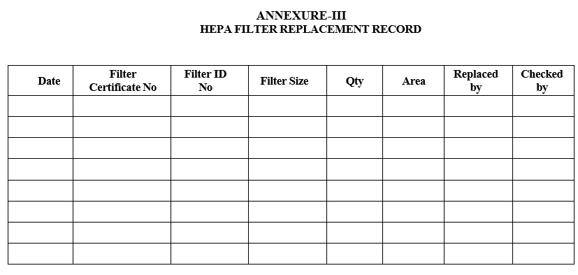
- In case the integrity test is not within the acceptable limit, replace the HEPA filter and record the same in Annexure-III.
Acceptance criteria:
- Any leakage shall not be greater than 0.01% of the upstream challenge aerosol concentration.
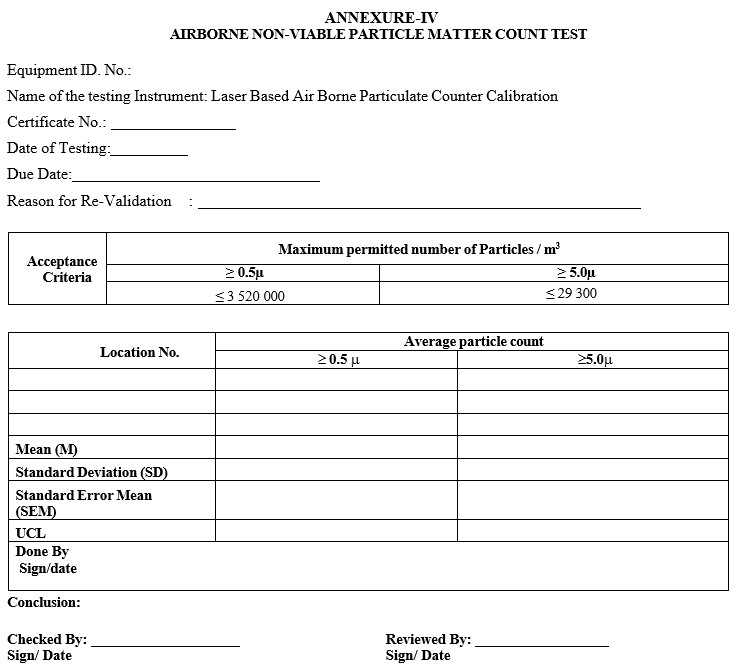
- Non –Viable Air Borne Particle Count Test
- Duly calibrated Air borne particulate counter shall be used and operations of air borne particle counter as per SOP.
- Ensure that the AHU is working for 1 hour before performing the test the equipment(s) are cleaned before performing this test.
- Calculate the number of locations using square root of the area in square meter.
- Divide the measuring plan in to equal grid cells based on number of sampling locations calculated.
- Perform the test adjusting the sampling time not less than one minute and flow rate shall be 1 ± 0.1CFM.
- Minimum sample volume 1CFM.Perform the test with minimum 3 cycles at each location repeat the above procedure at all the other locations as per the sampling location layout.
- Record the average particle count of the 0.5µ and 5.0µ in Annexure-IV.
- In case the non-viable airborne particle count test is not within the acceptable limit, clean the area and perform the test again.
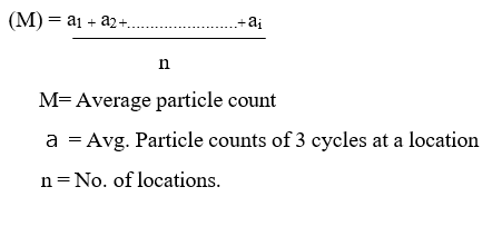
- Calculate the mean average particle count for all the locations. Calculate as per below formula.
Click the link to download word file copy of this document:
https://pharmaguidehub.com/product/revalidation-of-air-handling-unit-in-fluid-bed-processor-drier-equipment-and-automatic-coating-equipment/
Formula :
Formula for calculating the number of sampling point locations.

N= Minimum number of sampling locations (rounded up to a whole number) A= Area of the clean room or clean zone in square meters.
Formula for calculate the particle count UCL.
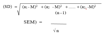
Upper Confidence limit (UCL)
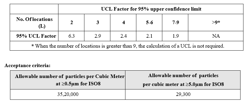
UCL = M + (UCL Factor X SEM)
UCL factor for 95% upper confidence limit for different number of locations is indicated in the following table.
- REFERENCES:
Not Applicable
- ANNEXURES:
| ANNEXURE No. | TITLE OF ANNEXURE |
| Annexure-I | Air velocity measurement |
| Annexure-II | Integrity Testing of HEPA Filters |
| Annexure-III | HEPA Filter Replacement Record |
| Annexure-IV | Airborne Non-Viable Particle Matter Count Test |
| Annexure-V | Validation Summary Report |
| Annexure-VI | Equipment AHU’s Revalidation Schedule |
ENCLOSURES: SOP Training Record.
- DISTRIBUTION:
- Controlled Copy No. 01 Head Quality Assurance
- Controlled Copy No. 02 Head-Engineering
- Master Copy Quality Assurance Department
- ABBREVIATIONS:
AHU : Air handling unit.
m : Micron.
ISO : International organization for standardization.
SEM : Standard Error Mean.
SD : Standard Deviation.
UCL : Upper confident limit.
CM/S : Cubic Meter per Second.
m3 : Cubic meter.
HEPA : High Efficiency Particulate Air.
m2 : square meter.
m : millimeter.
°C : degree Celsius.
NMT : Not more than
NLT : Net less than
SOP : Standard Operating Procedure
- REVISION HISTORY:
CHANGE HISTORY LOG
| Revision No. | Details of Changes | Reason for Change | Effective Date |
| 00 | New SOP | Not Applicable | To be written manual |
ANNEXURE-I
AIR VELOCITY MEASUREMENT
ANNEXURE-II
INTEGRITY TESTING OF HEPA FILTERS
ANNEXURE-III
HEPA FILTER REPLACEMENT RECORD
ANNEXURE-IV
AIRBORNE NON-VIABLE PARTICLE MATTER COUNT TEST
Click the link to download word file copy of this document:
https://pharmaguidehub.com/product/revalidation-of-air-handling-unit-in-fluid-bed-processor-drier-equipment-and-automatic-coating-equipment/