- OBJECTIVE:
To lay down procedure for the operation of DG set.
- SCOPE:
This SOP is applicable for the operation of DG set at {Company Name} {Company Location}.
- RESPONSIBILITY:
- Technical Assistant – Engineering is responsible for perform the activity as per the SOP.
- HOD/Executive – Engineering is ensure the compliance as per SOP.
- ACCOUNTABILITY:
Engineering Head
Head Quality Assurance
- PROCEDURE:
- Precautions:
- Check the engine oil level with dip stick oil gauge, if required top up engine oil up to the high level mark.
- Check the coolant level, if required top up the coolant up to the maximum level.
- Check and Ensure battery charging system and batteries.
- Battery voltage should not be less than 24V.
- Check cooling tower water level, if required top up the water up to the maximum level.
- STARTING PROCEDURE
- Release the emergency push button on DG power command control.
- Turn Off / Manual / Auto selector switch to Manual position.
- Press manual Run / Stop button to start the DG set.
- Check and ensure the oil pressure, voltage, and RPM in DG power command control panel.
- Release the emergency push button in the DG control panel.
- Close the ACB manually in the DG control panel.
- Close the DG incomer ACB in the power control centre.
- Switch ON the CT pump, ID fan in the utility MCC panel.
- Enter the readings in the DG set running parameters log sheet for every hour.
- STOPPING PROCEDURE
- Check and ensure the EB power supply presence & ensure the 3 Phase voltages should be in-between 415 – 420 Volts.
- Note down the final readings in the DG set running parameters log sheet.
- Open the DG incomer ACB in the power control centre and close the EB Incomer ACB in the power control centre.
- Switch ON the CT pump, ID fan in the utility MCC panel.
- Open the ACB of DG control panel manually and press the emergency push button.
- Run the DG set for 5 minutes in idle condition.
- Press manual Run / Stop button in the power command control to stop the DG set.
- Turn Off / Manual / Auto selector switch to “O” position.Press the emergency push button on DG power command control.
- Switch OFF the CT pump and ID fan in the Utility MCC panel.
- REFERENCES:
Not Applicable
- ANNEXURES:
| ANNEXURE No. | TITLE OF ANNEXURE |
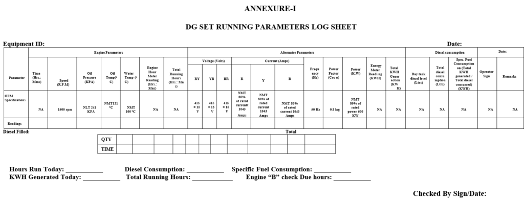
| Annexure-I | DG set running parameters log Sheet |
ENCLOSURES: SOP Training Record.
- DISTRIBUTION:
- Controlled Copy No. 01 Head Quality Assurance
- Controlled Copy No. 02 Head-Engineering
- Master Copy Quality Assurance Department
- ABBREVIATIONS:
DG Set : Diesel Generator Set
KVA : Kilo Volt Ampere
PCC : Power Command Control
RPM : Revolutions Per Minute
ACB : Air Circuit Breaker
CT : Cooling Tower
ID : Inner Draft
MCC : Motor Control Centre
EB : Electricity Board
SOP : Standard Operating Procedure
NA : Not Applicable
- REVISION HISTORY:
CHANGE HISTORY LOG
| Revision No. | Details of Changes | Reason for Change | Effective Date |
| 00 | New SOP | Not Applicable | To be written manual |
ANNEXURE-I
DG SET RUNNING PARAMETERS LOG SHEET