
- PROCEDURE:
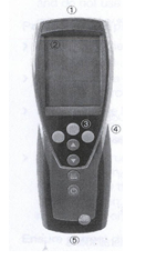
- Operation Keys
- Infrared, USB interface
- Display (light can be activated)
- Control buttons
- Rear: Battery and radio module compartment, holding magnet
- Probe socket(s)
- Key functions:
- Function button (3x): The function depends on the button assignment at the time.
- Change display of the 1st reading line In configuration mode: Increase value, select option.
- Change display of the 2nd reading line In configuration mode: Decrease value, select option.
- Print data 435-1/-3 only: If the Cyclical Printing function is activated, the programmed measuring program is started.
- Switch instrument on, switch display light on/off; switch instrument off (press and hold).
- Operating Procedure
- Plug-in probes must be connected before the measuring instrument is switched on so that they are recognized by the instrument.
- Insert the connector of the probe into the probe socket of the measuring instrument.
- Press measurement view is opened, and the current reading is displayed.
- The instrument is in measurement view, Press and hold (approx. 2s) until config.Is displayed.
- Select the desired profile with and confirm with OK.
- Units : The configuration menu is open, config.is displayed Units→ OK
- Press / ISO/US (to set the system) or a parameter (to set individually) and confirm with OK.
- Set the system of units or the desired unit with / and confirm with OK.
- Device : The configuration menu is open, config.is displayed.
- Instrument data.
- Date/Time
- Battery type
- Auto OFF
- Reset
- Pr Min Max
- K-factor
- Num holes
- Probe : The configuration menu is open, Config.is displayed.
- Probe→ OK → Te-Type→ OK.
- Select the desired probe type and confirm with OK.
- Language: The configuration menu is open, config.is displayed.
- Language → OK
- Measuring procedure:
- Press the Power button Switch ON the Instrument.
- Press and hold (approx. 2s) until config Is displayed.
- Select the Units by using / buttons, then press OK.
- Select the Velocity and select “m/s” or “fpm” according to the measuring requirement.
- Ensure the white → mark on the sensor head need to face against the direction of air flow.
- Hold the probe handle and move slowly towards the airflow source where air velocity to be measured.
- The display will show air velocity reading.
- Expose the Anemometer Probe below 1 to 2 inch of the air supply.
- Hold the probe for few seconds to get the reading stabilized.
- Switch to HOLD mode to hold on the reading.
- Record the reading, If another measurement has to be taken immediately after the first one, then wait for a few seconds and then expose the Anemometer probe at the required area.
- Press and hold (approx. 2seconds) button for switch off the instrument.
- Profile Setting: The configuration menu is open, config. Is displayed. Profile → OK.
- Select the desired language with and confirm with OK.
- Safety Instructions :
- Do not use the measuring instrument and probes to measure on or near live parts.
- Always use the measuring instrument properly and for its intended purpose.
- Do not use force.
- Do not expose handles and feed lines to temperatures in excess of 70°C unless they are expressly permitted for higher temperatures.
- Temperatures given on probes relate only to the measuring range of the sensors.
- Never store the measuring instrument, measuring cells together with solvents and do not use any desiccants.
- REFERENCES:
- Not Applicable
- ANNEXURES:
- Not Applicable
- ENCLOSURES: SOP Training Record.
- DISTRIBUTION:
- Controlled Copy No. 01 Head Quality Assurance
- Controlled Copy No. 02 Head-Engineering
- Master Copy Quality Assurance Department
- ABBREVIATIONS:
- USB: Universal Serial Bus.
- m/s : Meters per Seconds.
- fpm: Feet per minute.
- REVISION HISTORY:
- CHANGE HISTORY LOG
| Revision No. | Details of Changes | Reason for Change | Effective Date |
| 00 | New SOP | Not Applicable | To be written manual |