- PROCEDURE:
- Model Agilent 7890A with Agilent 7693 and Agilent G1888 auto samplers
- Gas chromatography (GC) is a powerful analytical technique used to separate and identify the individual components of a mixture.
- Check the cleanliness of working area, instrument and calibration status.
- Installing Capillary Column in Capillary Inlets:
- Install on the column a column nut and ferrule.
- Note that either a 0.4 or 0.8 mm.D graphite ferrule is used depending upon the column outer diameter.
- Position the column so that it extends approximately 4 to 6 mm from the end of the ferrule and the column nut (threaded end).
- Insert column ferrule and nut straight into the inlet base.
- Tighten the nut to finger-tight, then 1/4-turn more using a wrench. Ensure that the glass liner should be cleaned.
- Installing capillary column in FID:
- Install on the column, a column nut and ferrule.
- Note that either a 0.4 or 0.8 mm ID graphite ferrule may be used depending on the column outer diameter.
- Gently insert the column as far as possible into the detector (about 40 mm) until its bottom doesn’t attempt to force it further.
- Follow it with the ferrule and column nut.
- Tighten the finger-tight pull the column gently approximately 1 mm and then tighten the nut an additional 1/4 turn with a wrench.
- Leak test the installation at the column nut, both at ambient temperature and with the oven inlet and detector at operating temperature.
- If necessary tighten fitting(s) ferrule only to stop leakage.
- Operating procedure for capillary inlet with FID:
- Connect the required carrier gas line (Nitrogen/Helium) into the cylinder in the cylinder area.
- Open the column oven door by pressing the door key to the up position provided on the bottom of oven door.
- Remove the column from the column oven with the help of spanner.
- Fix the required capillary column into the split/split less injector and FID as per manual.
- Open the carrier gas cylinder nitrogen/helium in the cylinder area.
- Set the required pressure with the help of outlet knobs of respective gas in the gas station unit.
- Switch on the instrument provided on the rear bottom of the instrument and wait for 1 minute.
- After initialization “POWER ON SUCCESSFULLY”. will appear on LCD Screen.
- Press the Oven button on the system and press ON.
- System will be on. Open the zero air cylinder and hydrogen cylinder with the help of cylinder key in the cylinder area and set the required pressure for hydrogen gas with the help of outlet valve provided on the gas station.
- Open the zero air control valve provided on the bottom side of the cupboard.
- Then adjust the temperatures by pressing OVEN, INLET, DET. Button.
- In front detector auto igniters is there, it will ignite automatically when temperature reaches 150ºC.If it is not ignited FRONT DETECTOR FLAME OUT will appear on LCD screen. Before going for analysis, the column should kept for conditioning for at least 30min. this can be done by using above parameters.
- Switch on the computer and printer and wait for 2 minutes.Click Ctrl+Alt+Delete and enter lab user password.
- Start>Programs>Empower>Empower log or Empower log in desktop and wait for 2 minutes.
- Click on “Login…” Button. Empower login windows appear.
- Enter the allotted User name of the individual, password of the individual.
- Double click the “Browse project” button.
- “Browse project” window is displayed.
- Click to select GC related project then project window appears.
- Go to “Tools” on menu bar on the top and select run samples or press the run samples button on the tool bar.
- “Select System” window is displayed and click OK.
- Run samples button will start initializing.
- Run samples window is displayed.
- Select the required instrument method; from the “Instrument Method” window at the bottom.
- Click “Edit” to open the Instrument method.” Instrument Method” edit window is displayed.
- Verify general system parameters in settings button.
- The parameters are front inlet type, front detector type, back inlet type, back detector type, Enabling parameters are front injector, front inlet, column 1, front detector, channel 1, and front inlet none for head space analysis and pressure unites like psi ,Bar and KPa.
- Select oven button settings to the required parameters from the following: enable ‘Oven Enable, Cyro cooling enable, Temperature ramp enable’. Fill the required values in Maximum Temperature “____”, Equilibrium time “_____”, Initial Time “_____”, Initial Temperature “_____”.
| S. No. | Rate | Final | Hold Time | Total Time |
- Select front inlet button and set the parameters of Mode “split or splitless, Inlet Type: S/SL EPC, Select temperature enable, enter initial temperature, Enter Gas saver values, Set the required split/splitless ratio.
- Select column button enter the column dimensions in the selected field and select gas type is nitrogen or helium whichever is used as carrier gas. Setting “constant flow”. Set the Initial pressure 1.0.
- If front injector is selected in setting button then feed the required values in front injector button like sample pumps, plunger mode, viscosity delay, sample washes solvent washes pre and post of injection, wash mode.
- If head space analysis Switch on the Agilent G1888 net work Head space sampler and wait for few minutes it will check all parameters and comes to Ready mode.
- Press “Active Method”, Select “Zone temperature” by up/down arrow keys, press enter ‘ and enter Oven, Loop, Transfer line temperature with numerical keys and press ‘enter’ and press ‘clear’ as per requirements.
- Select “Event time” with up / down arrow keys and press ‘Enter’, enter GC cycle time, Vial equilibration time, Pressurization time, Loop fill time, Loop equilibration time and Inject time and press ‘enter’ and press ‘clear’.
- Select vial parameter with up/down arrow keys and press ‘Enter’ and enter First vial last vial and shaking mode and press ‘clear.
- Select front detector button, set Detector Type “FID”, Flame Enable, Enter set point temperatures as per requirement.
- Go to the pneumatics options in front detector button set Oxidizer flow (Zero Air) flow.
- Set Fuel (Hydrogen) flow and makeup flow and flow mode is constant makeup.
- Select channel 1 button, set the source “front Detector, Data sensitivity is “medium”.Go to “File” and select “Save”, to save the changes.
- To save the method with another name, select “Save as” and give the instrument method name in “Instrument Method” window. Click on Save.
- Close the Instrument Method Editor window by clicking on “X” on the right side top of the window.
- Create method set by click on “Single’ and develop methods ,Select instrument method and click next, add processing method, report method next add next and save method SET.
- To perform single injection; click on “Single” on the Quick set window.Enter the information like Vial No., Sample name, Function, Method set, Injection volume and Runtime in the sample-loading table.
- Go to “Inject” on the main menu bar on the top and select “Make injection” or press the “Inj” button below the Sample table; to start the injection.
- For performing injections of more than one sample, select “Samples” on the Quick Set Window.
- Fill the “Sample table” by “Auto Fill” mode.
- Select the “Sample Name” field in the Sample table and click on the right button of the mouse.
- Select “Auto Fill” from the menu.Enter the information like “Sample Name”, “Incrementing prefix” and “Incrementing suffix”, “Vials numbers to be injected” and click OK.
- Similarly Auto fill is done for “Method set”, “# of inj”, “inj.vol”, “Run time” fields by following the above procedure.
- The Sample table is filled with the above information.
- Go to “File” on main menu bar on the top and select “Save sample set method as”.
- “Sample set method” window is displayed. Enter the sample set name and press OK to save.
- Select run mode to “Run only” for data acquisition only.
- Select Run mode to “Run and process” for acquisition and processing.
- Select this mode only when processing method is created earlier.
- Select Run mode to “Run and report” for acquisition, processing and reporting.
- Select this mode only when processing and reporting methods are created and are included in the method set.
- Go to “Inject” on the main menu bar on the top and select “Run Sample set” or press the “Run” button (Green button) on the tools bar.“Run Sample Set” window is displayed.
- Press “Run” to start the sample set.
- The sample in the first row will be highlighted with red colour and the injections get started. Then sequence gets start.
- Procedure To Start The ‘Sample Set ‘ Using Head Space Sampler:
- Create the sample set in Empower as per the steps mentioned above.
- Create the method in Head space Sampler.
- Then click the green button in Empower Run samples window.
- Then waiting for injection message will come.
- Then start the Head Space sampler by using Start/Stop button.
- Procedure To Start The ‘Sample Set ‘ Using Auto Injector:
- Create the sample set in Empower.Then click green button in Empower Run samples window.
- After completion of the injections, clicks open the project window.
- Click the channel button in the views on the project screen.
- All the Channels are displayed.
- Alternatively select “All channels by date” filter to view all Channels.Select a completed injection in the channel view table.
- Go to “Tools” on the main menu bar on the top and select “Review”.
- Or click Start-review button in the tools. Review data: Project window appears.Review window is displayed with the chromatogram.
- Go to “Window” on the menu bar on the top and select “Processing method”:
- Enter the parameters Peak width, Minimum area, Minimum height, and Threshold value in the respective boxes of Integration table. Program the events if necessary.
- Click “Components” button. Enter “Component name”, “Retention time”, “RT window”.
- Click on “Suitability” button and select the Calculate the suitability results.
- Enter “Void volume” and select the required pharmacopoeia or “All” to calculate System suitability as per all pharmacopoeias.
- Close the “Processing Window”.
- Go to “Process” on the main menu bar and select “Integrate” and then “Quantitate”. Or press “Integrate” button and then “Quantitate” button on the tools bar.
- Now zoom the chromatogram to check for proper integration of peaks.
- If the integration is not proper alter the above parameters in the integration event table.
- Go to “File” and select “Save method as”.
- Enter the file name and click OK.Click File and ‘Save Result’.
- Then file ‘Exit’Click the Display results button in View of the project window.
- Select the above saved result of the sample in the Result view table.Click Preview button in the tools and select the required report or select report method from the Preview: Report Method Selection.
- The instrument starts creating the report and is displayed on the screen.Double click on chromatogram to modify the chromatogram scaling.
- Select User defined in scaling type:
- Feed required scale parameters, like X-start, Y-start, X-end, Y-end. Double click the Peak result table below the Auto scaled chromatogram to modify the table format by selecting the required parameters.
- Select the required peak results by double clicking the parameters like: Component name, retention time, area, area %, height, height % in the peak fields, Channel name, Date acquired, Injection from the Sample fields System suitability parameters like USP Tangent, USP Tailing, and Resolution from system suitability fields.
- Click file and save.
- Click Printer button to print the current report.
- Click File exit.
- Go back to the Quick set control window and select Run and Report mode against square to enable the continuous printing of the results after completion of the subsequent injections.
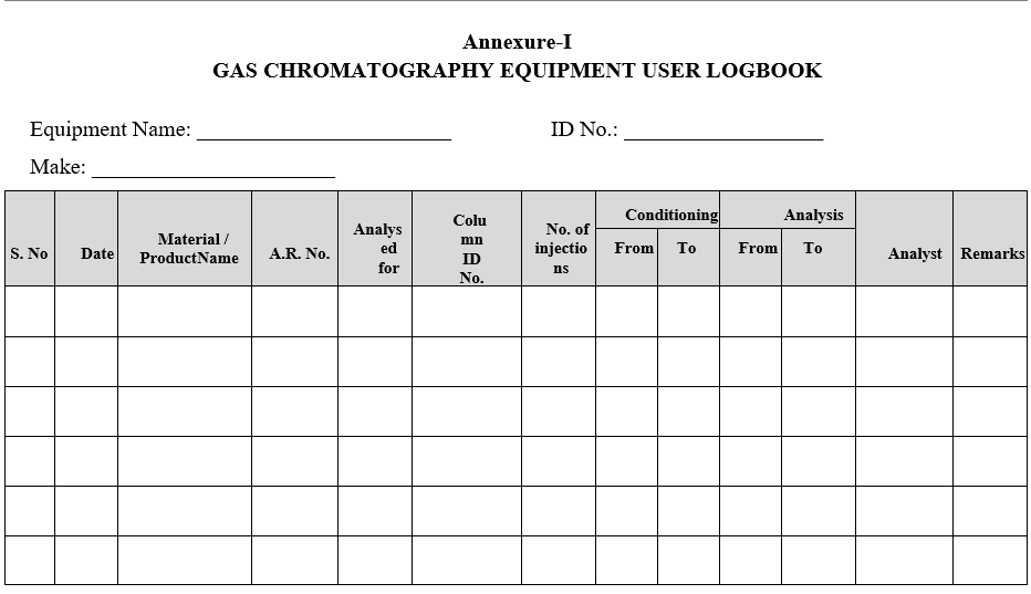
- Enter the usage details in user log book as per Format-I.
- ANNEXURES:
| ANNEXURE NO. | TITLE OF ANNEXURE |
| Annexure-I | Gas Chromatography Equipment User Log Book |
Annexure-I
GAS CHROMATOGRAPHY EQUIPMENT USER LOGBOOK