OBJECTIVE:
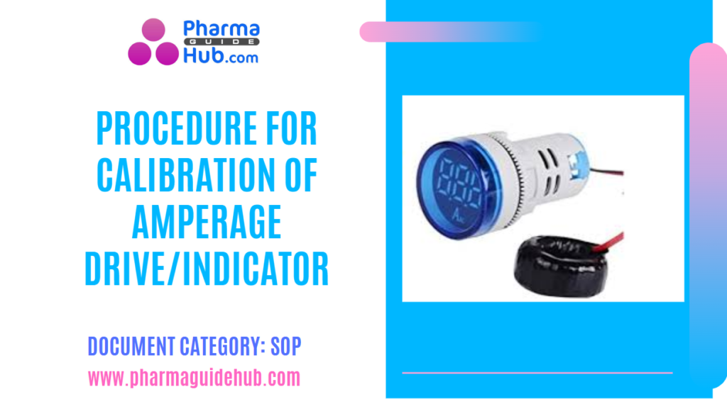
To lay down a procedure for calibration of Amperage Drive/Indicator.
SCOPE:
This SOP is applicable to the procedure for calibration of Amperage Drive/Indicator at {Company Name} {Location}.
RESPONSIBILITY:
Engineering Head/designee is responsible for compliance of SOP.
Officer/Executive/Designee: shall be responsible for following the procedure as per SOP.
ACCOUNTABILITY:
QA Head shall be Accountable for implementation of SOP.
PROCEDURE:
About Amperage Drive/Indicator
An Amperage Drive/Indicator is a device that displays the amount of current (measured in amperes or amps) flowing through a circuit. It’s often used to monitor the electrical load on a system and ensure it’s operating within safe limits.
Key Components:
Amperage Sensor: This component measures the current in the circuit. It can be a variety of devices, including:
Current Transformer (CT): A non-invasive sensor that measures current by detecting the magnetic field around a conductor.

Image accrediated to: https://www.electronics-tutorials.ws/transformer/current-transformer.html
Shunt Resistor: A low-resistance resistor that is placed in series with the circuit. The voltage drop across the resistor is proportional to the current flowing through it.

Image accrediated to uk.rs-online.com
Hall Effect Sensor: A sensor that generates a voltage proportional to the magnetic field around it. This voltage can be used to measure current.

Amperage Indicator: This component displays the measured current. It can be:
Analog Meter: A traditional meter with a needle that moves across a scale to indicate the current level.

Digital Meter: A more modern meter that displays the current value as a numerical readout.

image accrediated to: meters.uni-trend.com
Procedure:
Follow the procedure of respective SOP before and after completion of the calibration activity.
Ensure that the standard True RMS clamp meter and accessories are cleaned condition.
Ensure that the standard True RMS clamp meter within the validity period.
Ensure that the standard True RMS clamp meter battery is fully charged.
Calibration of Amperage Drive/Indicator:
- Find the drive outgoing cable location to the equipment and connect the Standard True RMS clamp meter current Jaws.
- Select the standard True RMS clamp meter suitable Amperage range with the rotatable knob of the instrument.
- Switch on the Equipment and run the motor desired speed.
- Measure the Drive/Indicator Amperage reading by using Standard True RMS clamp meter and confirm the Drive/Indicator display reading.
- Allow a few seconds for the Drive/indicator to stabilize the reading of Standard and specimen Amperage Drive/Indicator.
- In case of any discrepancy is observed in the under calibrating Amperage Drive/indicator then adjust the indicator for necessary correction.
- Run the equipment at different speeds and note down the reading with the Standard True RMS clamp meter.
- Follow the same mentioned in above and take the readings slow and fast run of the equipment and measure the Particular Amperage Drive/indicator.
- Acceptance criteria for the Amperage instruments are +/- 5% Amps with Standard reading.
- The standard Digital True RMS clamp meter should be calibrated once in a year.
- Sign off the calibration certificate by the respective person’s responsibility.
- File the Reviewed Calibration Certificate with Calibration Lab.
- Based on the Calibration results prepare the Calibration status label.
- Affix/tag the Calibration status label as per the SOP of Calibration of Equipments /Instruments.
- The Amperage instruments are calibrated as per the Master calibration schedule
REFERENCES:
Not Applicable
ANNEXURES:
| ANNEXURE NO. | TITLE OF ANNEXURE |
| Annexure-I | Calibration of Equipments/Instruments |
DISTRIBUTION:
Master Copy : Quality Assurance Department
Controlled Copy No. 01 : Head Quality Assurance
Controlled Copy No. 02 : Head Engineering
ABBREVIATIONS:
| No. | : | Number |
| RPM | : | Revolutions per minute. |
| SOP | : | Standard Operating Procedure |
| RMS | : | Route mean square |
REVISION HISTORY:
CHANGE HISTORY LOG
| Revision No. | Details of Changes | Reason for Change | Effective Date |
| 00 | New SOP | Not Applicable | To Be Written Manual |
Annexure-I
CALIBRATION OF EQUIPMENTS/INSTRUMENTS


