
- Operating Procedure of Particle Size Analyzer:
- Switch on the power supply for the optical unit and ensure that the main power input socket (located at transmitter and panel) is properly set to the transmitter part of the optical unit.
- The Transmitter contains the laser and electronics that produce the laser beam that is used in the measurement of the samples.
- Turn the laser on/off power key clockwise.
- Press on/off power switch off the optical unit.
- Ensure that the laser power indicator LED is ON indicated by the blue light.
- Switch on main power for dispersion unit controller.
- Ensure that the connector between dispersion unit controller and small volume dispersion unit is properly connected.
- Switch ON for the dispersion unit controller ensures that the pump speed LCD display shows 0000 rpm.
- Ensure that the tubes with small volume sample dispersion unit which are connected to sample cell in port and out port are connected properly to avoid leak during analysis, ensure that the one end is connected to drain exit point properly and other end is to drain waste.
- Ensure that the communication cable is properly connected between the computer communication points and the computer.
- Switch on the PC monitor, monitor displays window XP screen after 2 min, ensure that the matersizer 2000 icon appears on the monitor.
- Measuring sample with small volume dispersion unit:
- Wash 3 to 4 times the sample dispersion unit and the flow cell and the tubings thoroughly with the solvent in which the analysis is being carried out, after washing fill the dispersion unit with the medium, adjust the stirrer speed knob to a certain numerical value as mentioned in the respective product STP to obtain uniform stirring through the medium.
- Double click size icon mastersizer 2000 mastersizer 2000 window appears which prompts for the user to enter his password, enter the password and click on OK, The user is accessible for the use of the instrument.
- Click set up set hardware window will appear.
- Click on configure on the menu bar , a list of options appears , click on the NEW SOP which prompts for the SOP creation wizard , go to next select the sampling unit based on the dry or wet method as mentioned in respective product STP, For dry method select SCIROCCO 2000A and for wet method select HYDRO2000SMA, then click on next which prompts a window where the user can enter the details like material name and dispersant used , if the material and dispersant is already existing then simply select, In other case in order to add a new material or dispersant click on add button which prompts a window where the user can enter the material name and properties like refractive index and absorption index required for that product then click on the dispersant button select the dispersant of our interest if it is already there in the list, otherwise click on the add button and enter the details of the dispersant.
- Then click on ok go to next and save the SOP with either the material name or the material code followed by wet or dry method.
- From the menu bar select measure, which prompts for START SOP where the user can start the analysis, before staring the sample analysis from the menu bar itself click on manual which ensure the background is correct shown by anti parabolic curve.
- Click align optics icon measure align window will appear click start button then the instrument will automatically align.
- Aligned the laser power reading should show a value greater than 75% T.
- If the laser power reading showing less than 75%T, wash the flow cell thoroughly or clean the flow cell window by following point no Again .
- Click next button then measure background window will appear.
- Click start button and background measurement automatically start, the start button will Change to the stop while the measurement if you need to when the button changes back to start the measurement is complete.
- Click next button, then measure- inspect window will appear.
- Prepare the sample solution as per the GTP/STP.Click start button and the instrument will start to measure the obscuration.
- Using the dropper add the sample to the dispersion unit drop wise and allow the sample to thoroughly mix with dispersant.
- Add enough sample and adjust the obscuration value between 5-25% for samples which have particle size greater than 20µm and 1-10% for the samples which have a particle size Between 1 to 20µm and for those samples which have a particle size lesser than 1µm adjust the obscuration value between 1-5%.
- And for dry samples adjust the obscuration between 0.5–6%.Click next button, measure sample window will appear.
- Click start button and measurement will start, the start button will change to stop allowing the user to stop the analysis if the user does not get the correct particle of interest, and once the measurement is complete the button will change to back to start.
- Click next button analysis of data window will appear.
- Analysis table will appear along with the distribution graph on the monitor.Click save record icon, which allows to save the data /record
Click the link to download word file copy of this document:
https://pharmaguidehub.com/product/operation-of-particle-size-analyzer/
- Measuring samples with dry feeder:
- Open the mastersizer sample area door and remove the front and near accessory panels and fix carefully the dry unit to the mastersizer receiver mount.
- Position the exhaust end of the air cell through the rear accessory opening and mount the air cell on to the front of the lens using the three pin location.
- Rotate the locking lever downward to secure the air cell in position.
- Close the mastersizer sample area door.
- Push the air cell extension onto the air cell.
- Find a 320 mm length of the sample tubings from the accessory case, push one end of the sample tubing through the hole in the sound reduction cover and connect it to the air cell extension connector.
- Push the sound reduction cover into the connector with the mastersizer.
- Push the other end of the sample tubing on to the sample outlet connector of the dry feeder.
- Ensure that the compressed air is switched off.
- Connect the 3M length of the flexible tubing to he supply point of compressed air by pushing firmly into the connector.
- Connect to the other end of the flexible tubings to the side panel connector marked air in of the dry powder feeder unit.
- Find 1.4 M length of flexible tygon tubing and connect one end to the air cell vacuum monitor of the side connector panel of the dry powder feeder.
- Connect the vacuum unit power lead to the side panel connector vacuum power out let socket connect the other end of the lead to the vacuum unit.
- Find cab2001 gray colored cable from the accessory panel, connect the other end to the connector marked digital I/O of the side connector panel of the dry feeder.
- Connect the exhaust end of the air cell and the vacuum unit hose by means of the optional 90-extension tube.
- Check all connections for leak.Open the Perspex lid on top of the dry powder feeder unit.
- Obtain the sieve and ball bearing from the accessory case.
- Fill the required sieve half full of bearings.
- Place the sieve in to the sample cone.
- The hopper should be positioned so that the tongue is across the centerline of the sieve.
- Tighten the locking screw so that the hopper can be moved manually.
- The hopper has a pair of gates which slide to adjust the gap between them the gap should be not more than 3 to 4 mm.
- Close the Perspex lid.Switch on compressed air and vacuum unit.
- Open the Perspex lid and place enough sample in to the hopper close the Perspex lid.
- Select proper air flow / vacuum sample feed rate and pressure in air flow cell by means of adjusting respective knobs provided on dry powder feeder to get value.
- Cleaning the cell windows:
- Make sure that the cell has been drained of dispersant and remove the cell assembly from the mastersizer bulk head by releasing the locking lever.
- Disconnect the sample tubes from the cell.Locate the two pegs on the window tool in to the two holes on the relating ring.
- Rotate the window tool anticlockwise and remove the rin.
- If the o ring did not come out of the window then carefully remove it with a pair of tweezers.
- Tip the window out of the cell on to a clean paperReassemble the window by first placing the window in to the retainer then pushing the o ring in to the position.
- Screw the window ring back in place, ensure the window is fully home in the mount and not held by the o ring otherwise the window will move when the dispersant flow speed is changed causing the system to mis-align.
- Replace the cell onto the mastersizer and reconnect the sample tubes if applicable, to check the integrity of the cell, pump dispersant through it, ensure that no dispersant leaks from the cell or sample connectors.
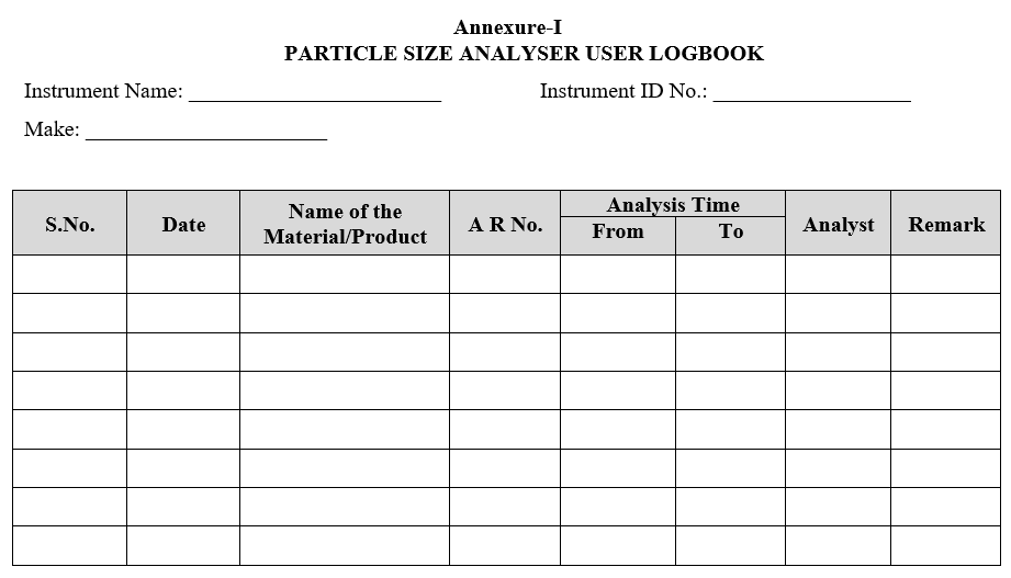
- Enter the details of usage in the logbook.
- ANNEXURES:
| ANNEXURE NO. | TITLE OF ANNEXURE |
| Annexure-I | Particle Size Analyzer user logbook |
Annexure-I
PARTICLE SIZE ANALYSER USER LOGBOOK
Click the link to download word file copy of this document:
https://pharmaguidehub.com/product/operation-of-particle-size-analyzer/
If some one wants expert view regarding blogging and site-building afterward i recommend him/her to pay a visit this weblog, Keep up the fastidious work.