- PROCEDURE:
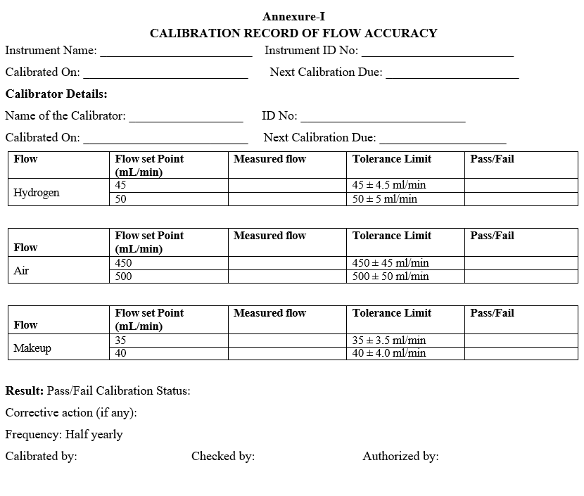
- CALIBRATION OF FLOW ACCURACY:
- Select detector flow and set it to the specified value listed in the result Table (Annexure-I)
- Ensure that all other detector flows are “OFF”.After completing appropriate preparation steps for the calibration mass flow meter being used ( i.e. Gas selection, purge, and zero).
- Connect the flow meter to the detector exit and measure flow.
- Allow time for flow meters” reading to stabilize.
- Record the flow value displayed on GC front panel in the results table.
- Record the measured flow value displayed on flow meter in results table (Annexure-I).
- Calculate the flow difference between displayed value and measured value and record the results table (Annexure-I).
- Turn flow OFF.Repeat the steps above for each remaining detector flow.After all flows have been measured.
- Remove the flow Cap from the detectors base.
- Acceptance criteria: the difference between measured flow and set flow should not be more than ± 10%.
- Record the details in annexure-I.
- Calibration schedule: Once in six months and after any major maintenance Job.
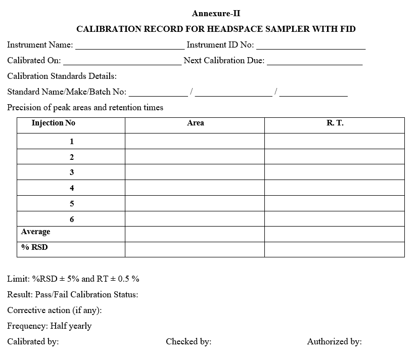
- CALIBRATION OF HEADSPACE SAMPLER WITH FID DETECTOR:
- Fix the column from capillary inlet to FID.
- Chromatographic parameters
- Column: Fused silica column 30 m long 0.32 m internal diameter with 1.8 micrometers film of 6% Cynopropyl Phenyl. 94% dimethyl polysiloxane.
- Inlet temperature 120°C
- Carrier gas: Helium
- Oven temperature: 60°C (Iso thermal)
- Flow mode: Constant Flow
- Detector Temperature: 200°C
- Column Flow: 0.8 ml/min
- Hydrogen Flow: 45 ml/min
- Air flow :450ml/min
- Make up flow :30ml/min
- Mode: Split
- Split ratio: 1:50
- Stop time: 15 min.
Head space parameters
- Incubation temperature: 80°C
- Agitator Speed: 500 rpm
- Incubation Time:20 min
- Agitator on time: 10 sec
- Agitator off time: 10 sec
- Flush Time: 2.0 min
- Syringe temperature: 90 °C
- Pressurization Time: 0.08 min
- Injection Volume: 1000 µL
- Fill speed: 500 µl /sec
- Fill stroke: 1
- Injection speed: 500 µL/sec
- GC Cycle Time :20 min
- Sample preparation: prepare 0.4 % v/v of Ethanol in water.
- Prepare six vials each contains 2 ml test solution. Seal the vial with PTFE septa and cap, place in the headspace analyzer. Run the experiment.
- Retention time for ethanol shall be about 4.0 min.
- Acceptance criteria:
- RSD for peak area should not be more than 5.0 %
- RSD for retention time should not be more than 0.5%
- Record the details in Annexure-II.
- Calibration Schedule: Once in six months and after any major maintenance Job.
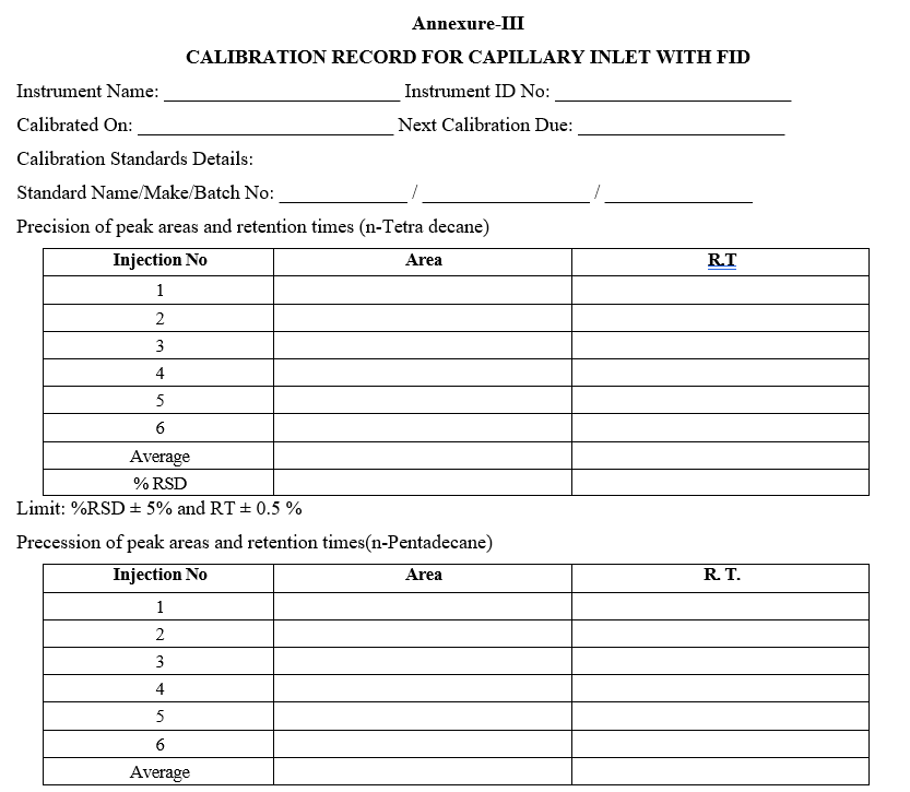
- CALIBRATION OF CAPILLARY INLET WITH FID:
- Fix the column for capillary inlet to FID.
- Chromatographic parameters
- Column: HP –5, 30 mx0.32 mm ID x 0.25µ
- Inlet temperature: 250°C
- Carrier gas: Helium/Nitrogen
- Flow mode: Constant pressure
- Inlet pressure column 25 psi
- Detector Temperature: 300°C
- Injection Volume: 1 µL
- Column Flow: 0.8 ml/min
- Hydrogen Flow: 45 ml/min
- Mode: Split less
- Air Flow: 450 ml/min
- Makeup Flow: 7 ml/min
- Run time: 8.5 min
- Oven temperature Program: Initially held at 60°C then raised to 90°C at 25°C/min. Then again increased to 170°C at 15°C /min. Hold at 170° C for 2 min.
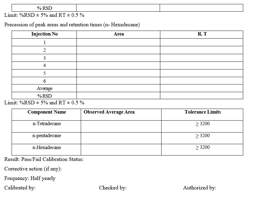
- Procedure: Inject the sample 6 times as per the procedure and calculate the RSD for retention times and peak areas of individual peaks.
- Acceptance criteria:
- RSD for peak area should not be more than 5.0 %
- RSD for retention time should not be more than 0.5%
- The average area of individual peaks should be greater than the value mentioned in the annexure-III.
- Record the details in calibration record in Annexure-3
- Calibration Schedule: Once in six months and after any major maintenance Job.
- CALIBRATION OF DETECTOR LINEARITY FOR FID:
- Chromatographic parameters:
- Column: Fused silica column 30 m long 0.32 m internal diameter with 1.8µ
- Injection temperature 190°C
- Carrier gas: Helium/Nitrogen
- Flow mode: Constant Flow
- Detector Temperature: 250°C
- Hydrogen Flow: 45 ml/min
- Air Flow: 450ml/min.
- Make flow :30ml/min
- Column Flow: 1mL/min
- Mode: Split
- Split ratio: 1:50
- Injection Volume: 1000 µL
- Run time 20 min.
- Oven temperature Program: Initially held at 70 °C for 10 min. Then raised to 260°C at 70°C/min and Hold at 260° C for 5 min.
Head space parameters
- Incubation temperature: 120°C
- Agitator Speed : 500 rpm
- Incubation Time:30 min
- Agitator on time : 10 sec
- Agitator off time: 10 sec
- Flush Time : 2.0 min
- Syringe temperature : 130 °C
- Pressurization Time: 0.08 min
- Injection Volume :1000 µL
- Fill speed : 500 µl /sec . Fill stroke: 1
- Injection speed: 500 µL/sec .
- GC Cycle Time: 25 min
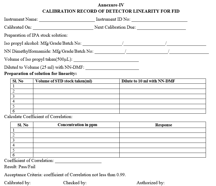
Preparation IPA stock solution :
- Take 500µl of IPA into a 25ml flask having about 20 ml of NN-DMF and then dilute it to volume with NN-DMF and mix well.
Preparation of solutions for Linearity.
| S. No | Volume of STD stock (ml) | Dilute to 10 ml of NN- DMF | |
| 01 | 1 | 10 | |
| 02 | 2 | 10 | |
| 03 | 3 | 10 | |
| 04 | 4 | 10 | |
| 05 | 5 | 10 | |
| 06 | 6 | 10 | |
- Pipette 5 ml of each solution into individual vials. Fit them with a septum and crimp cap and then seal it and inject.
- Calculate the coefficient of correlation.
- Acceptance criteria: Coefficient of correlation NLT 0.99.
- Calibration: Once in six months and after any major maintenance Job.
- Record the Details in annexure-IV.
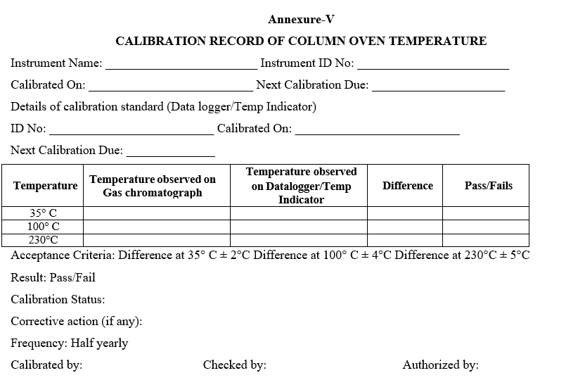
CALIBRATION OF COLUMN OVEN TEMPERATURE TEST:
- Set the oven temperature to 35°C and wait for at least 5 min to stabilize the oven, take the temperature reading from the data logger and record the temperature.
- Set the oven temperature to 100 °C and wait for at least 5 min, after the oven gets Stabilized record the data logger reading in the annexure.
- Set the oven temperature to 230 °C and wait for at least 5 min, after the oven gets Stabilized record the data logger reading in the annexure.
- Acceptance criteria:
- The difference at 35°C should not be more than 2°C from the set value.
- The difference at 100°C should not be more than 4°C from the set value.
- The difference at 230° C should not be more than 5°C from the set value.
- Record the details in Annexure-V.
- Calibration schedule: Once in six months and after any major maintenance Job
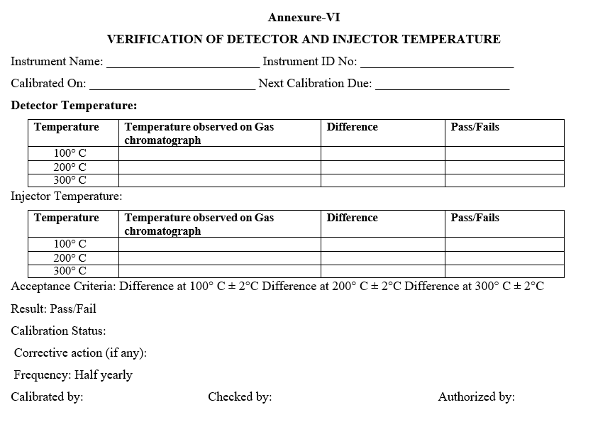
- VERIFICATION OF DETECTOR AND INJECTOR TEMPERATURE:
- Detector:
- Set the detector temperature to 100°C and wait for at least 15 min and record the Temperature in Annexure -VI.
- Repeat the above step for remaining temperatures 200°C and 300°C.
- Injector:
- Set the injector temperature to 100°C and wait for at least 15 min and record the temperature in Annexure-VI.
- Repeat the above step for remaining temperatures 200°C and 300°C.
- Acceptance criteria:
- The difference at 100°C should not be more than 2°C from the set value.
- The difference at 200°C should not be more than 2°C from the set value.
- The difference at 300°C should not be more than 2°C from the set value.
- Calibration schedule: Once in six months and after any major maintenance Job.
- ANNEXURES:
| ANNEXURE NO. | TITLE OF ANNEXURE |
| Annexure-I | Calibration record of Flow accuracy |
| Annexure-II | Calibration record for Headspace sampler With FID |
| Annexure-III | Calibration record for capillary inlet with FID |
| Annexure-IV | Calibration record of Detector Linearity for FID |
| Annexure-V | Calibration record of Column oven temperature Test |
| Annexure-VI | Verification of Detector and Injector temperature |
Annexure-I
CALIBRATION RECORD OF FLOW ACCURACY
Annexure-II
CALIBRATION RECORD FOR HEADSPACE SAMPLER WITH FID
Annexure-III
CALIBRATION RECORD FOR CAPILLARY INLET WITH FID
Annexure-IV
CALIBRATION RECORD OF DETECTOR LINEARITY FOR FID
Annexure-V
CALIBRATION RECORD OF COLUMN OVEN TEMPERATURE
Annexure-VI
VERIFICATION OF DETECTOR AND INJECTOR TEMPERATURE